

Feeding mechanisms of the filling press and its mechatronic simulation
The process is developed progressively, using press queues for this purpose. Deep fillings are made in the initial presses and in the last cutting and finishing operations. The systems of transport of pieces from one press to another have varied over time, from the initial work carried out by the operators, and later through automated systems, leaving the staff aside. The last step in this development is the transfer press. We can say that Transfer is a unique press that makes a progressive sausage in several steps, using the transfer mechanism to transport the pieces from one step to another.
This type of presses double at least productivity. Consequently, the transfer mechanism must move the heavy weights quickly and accurately. These functions can be performed by mechanical or electrical transfer.
Mechanical transfer of mechanical transfer
The electric motor of the mechanical presses is attached to a high inertia wheel that, without just varying its speed, provides energy in the moments you need. Due to its dimensions, the engine and the wheel are located at the top of the press. On the other hand, to facilitate the tuning of the feeding system with the movement of press carts and carry out the security measures, the transfer mechanism is connected to the brake clutch used to supply power to the inertia wheel. In this way you can take advantage of the power of the wheel and no other motor is needed.
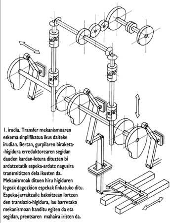
Figure 1 shows the simplified scheme of the transfer mechanism. In it it is observed that the rotation movement of the wheel is transmitted from the two axes that are joined by the cardinal following the reducer to the main axis of levas. The law of three movements (forward/back, up/down and zabadu/closed) containing the mechanism will fix the corresponding levas. The translation movement that is achieved in each foaming increases in the mechanism of the four bars and then reaches the press table.
To meet the productivity and manufacturing tolerances required by the market, transfer mechanism movements must be very fast and accurate. These characteristics are defined mainly by the cam profile: the input and output should be smooth and high-speed movements. In most cases, due to the high height of the presses, flexibility and small play are difficult to maintain. Consequently, the movements that are obtained produce vibrate to the detriment of the tolerances of manufacture. Although the vibrations are a consequence of the complex functions of speed, they present a dominant trend of growth associated with speed, limiting the productivity of the entire machine.
The use of electronic transfer is spreading with the intention of dealing with all these drawbacks.
Electronic transfer Electronic transfer
The main advantage of this option is the simplification of the mechanism and its manufacturing flexibility.
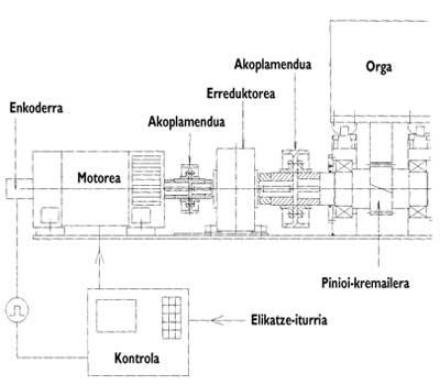
The bad aspect is found in the complexity of the electronic motor. As can be seen in figure 2, the other electric motor will be used around the press table. Therefore, the length of the mechanism, and therefore the flexibility and the games, are reduced considerably. The cams and the mechanisms of the four bars disappear and their function will be governed by the electronic regulation of the motor. The components that appear now after the reducer are the flexible coupling and the zipper and the sprocket.
However, the electronic transfer, in addition to control problems, also presents problems of synchronism and security.
Mechatronic simulation
As discussed above, the behavior of the feeding mechanism is decisive for the proper functioning of the transfer press. Moreover, these systems adapt to the needs of the client, demanding an “ad hoc” design and taking into account the high cost of the transfer press, any failure has a great economic impact.
Therefore, in the development of new designs, the suitability and need for simulation predominates. However, its usefulness can be extended to the detection of problems and to the prior confirmation of improvements in the products made.
The drills are based on models. For the development of models typical of the areas of Mechanics, Electronics and Hydraulics, for a long time there are specialized techniques. However, if one wants to simulate a detailed behavior in a model of an area of this type, or if one wants to carry out a model of system of components of different areas, that is, the development of mechatronic models, becomes a problem.
The development method of the Bond Graph models allows to overcome these problems. The formulation of this model is based on the exchange of energy, so for any field the same “language” is used. On the other hand, the graphic representation of the model offers experts in different fields the possibility to understand it instantaneously and to make tangible change proposals. In addition, the software available on the market, after checking that the Bond Graph model is correct, automatically generate equations that indicate the dynamic behavior of the system and, in short, integrate to carry out the simulation.

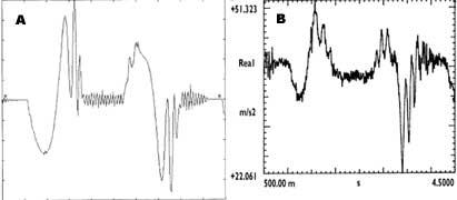
An example can be seen in figure 3. This example corresponds to the mechanical transfer model and has been taken into account the contacts of cams, flexibilities and games. Comparing with the measured acceleration, the quality of the model is evident.
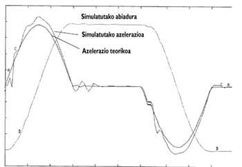
In electronic transfer, after aligning the Bond Graph model around the equilibrium point, other tools available for Control Design (Matlab, Matrix-x, etc.) are used to tune the control parameters. You can then enter the parameters set in the Bond Graph model and obtain specific simulations of the entire system. The conclusions of this process can be seen in Figure 4. It has been carried out for an electronic transfer and simulated displacements and accelerations simulating flexibilities, games and control simultaneously.
Conclusions of the conclusions: Conclusions
There are currently models that allow the realization of complex and/or mechatronic products “well and at first”, as well as methods for their development and methods to carry them out. The transfer simulations indicated have revealed the strength of the development method of the Bond Graph model in this type of systems.
The press author FAGOR ARRASATE has adopted these methods of simulation by IKERLAN, thanks to the European project OLMECO promoted by the European Union and the project “Simulation of Mechatronic Systems in Machine Tool”, co-financed by CICYT and the Basque Government.
Zu idazle
Zientzia aldizkaria