

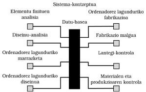
Computer design and machining (CAD/CAM)
This article is completed with the aim of clarifying the contents of the most technically known CAD/CAM acronym. Since the topic is broad and we do not intend to move in great depths, the process followed in this technique will be represented step by step by some examples.
Although the term design is mentioned here, at the moment in most companies CAD is limited to interactive drawings in two dimensions.
To take advantage of the possibilities offered by the CAD technology, from the interactive drawing you should follow the following steps:
- Preparing menus for tables.
- Complete the symbology, both standard and own symbols (boxes, logos, etc. ). ).
- Set attributes for removing parts lists.
- Use parametres for similar parts.
- Use the graphic language within the CAD to create new functions, perform calculations, etc.

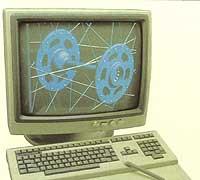
When designing the new element, it is best to base it on a three-dimensional geometric model.
This three-dimensional geometric model can be worked with yarn, surface or solid. This does not mean that they are used only with threads, surfaces or solids. Many or most of the time they are mixed.
In the thread model the shape of the body is represented by the edges. The results of the cuts will therefore be points.
On surface models, mesh and colours are used to express body shape. The intersection between surfaces or between surface and plane is usually a line.
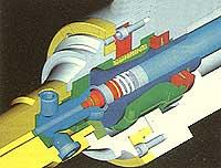
In solid models, the element appears as it is with colors. When cutting is done, the result is a surface.
The solid model allows to investigate the image: colors, shadows, different points of light, feces, flashes, interferences and transparencies.
A three-dimensional model, superficial or solid, allows to analyze its physical characteristics: surface, volume, mass, weight, center of gravity, moment of inertia and main axis of inertia.
If instead of a single element the mechanism is investigated, there is also facility to analyze other characteristics. For example: suitability for mounting, adjustments, tolerances, etc.
If you want to perform a finite element analysis (CAE), tensions that appear within the model, distributions, deformations, etc. is scaled for analysis.
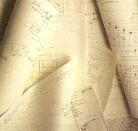
After these three steps (conceptual design, consolidated design and feature study), we are prepared to make drawings or screenshots (hard copy) of this model or element.
These plans will be drawn by a plotter or rayador in which the views, measurements, perspectives, cuts, details and strips of materials that you want to show are made almost automatically.
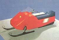
Technological advances have been important, both for the improvement of screens and for the creation of thermal printers, and for the decrease in the prices of these tools, both in the field of marketing and technical documentation, facilitating the use of realistic images.
In this way we can sell the product before its manufacture and adapt it to the needs of customers.
CAM
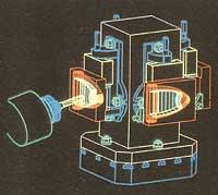
If it is necessary to use a numerical control to work, do or manipulate the part, it is best to use the geometric data generated in the CAD to program.
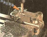
Suppose that part has to be machined. Therefore, taking into account the part geometry, we must fix the tool geometry, tooling and fixings, technological conditions and machine parameters. Once this is done, the process will be defined taking into account the tool inputs, outputs and jumps, machining tolerances and different forms of machining.
Once each operation is defined, the path followed by the tool is checked through the screen.
After complete machining the whole process will be verified. Make appropriate modifications, creating new operations, modifying order and parameters, etc.
In the process auxiliary operations will also be established: program number, interbal between blocks, formation and stopping of the axis and drill, end of the program, cycles, etc.
Once the process is defined as follows, the System automatically performs a neutral CLFILE or APT file. This neutral program must be processed to obtain the machining program according to each control and machine.
To communicate the numerical control of the machine and the program obtained by the computer, the DNC communications management program is used.
The DNC program includes reading file lists, receiving, sending, deleting or copying programs, managing machine parameters and tools, and running the program.
When the programs are large and considering that the memory of the numerical control is small, this program runs in infinite ways. That is, part of the program is sent from the computer to the control and receives the next part of the computer before that buffer or stack is emptied during its execution. This way you can make an unlimited program without cuts.
Expert systems are increasingly being used in the field of CAM. We will cite only some of the possibilities that offer us: automatic roughing, appearance of the places to be treated, placement of curves and control surfaces, control of the relative position of the tool and selection of tools and technological parameters.
Finally, the information of the geometric model used in the design can be used in the following manufacturing phases: testing and inspection of prototypes and quality control.


Zu idazle
Zientzia aldizkaria