CAD to CAM: manufacturing systems
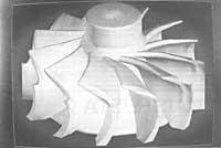
We have not been surprised though. In fact, we have long learned to express the names of organizations, especially by acronym of political parties (HB, PNV, PSOE,...) as well as companies (FAGOR, RENFE, CAF,...) or any other association (DYA, EUTG, UEU,...).
Gradually, in addition to abbreviations, acronyms increasingly contain complete definitions of new objects. For example, a new tax has been called VAT (Value Added Tax), a disease such as AIDS (Acquired Immunodeficiency Syndrome). Creating new words is difficult for modern society.
However, we still have a lot to do. Currently, in any newspaper in England we can read lines such as: "The PM toki the MPs that any PC for VIPs should include IDs in thei CVs". Listening on the radio, the effect is even more enigmatic. And if you look at the acronym vocabulary that is nowhere, we find that PM Prime Minister, MP Member of Parliament, PC Policeman, VIP Very Important Person, ID Identity Card and CV Curriculum Vitae. By then, however, we would have realized that the news of the weather is being given, and for the next, of course!
The awake reader may say that it is not possible to hear such phrases, arguing that in the UK there is no Identity Document. And it is true, for the moment, but this makes even more terrifying the flood of acronyms: the object has been baptized before birth!
So in ordinary life, what can not be expected of the technological world, where each article launches a new sympathetic concept. In a few years, in the field of engineering, CAD (Computer Aided Design), computer-aided design, and CAM (Computer Aided Manufacturing), computer-aided manufacturing, have become words of everyday life. And the concepts that were initially abstract have come true today. For example, when we talk about CAD, we no longer have in mind the inaccurate image of a computer program. We reunite with the screen, mouse and graphic table, which due to their flexibility have become a success in the market of CAD systems.
CAE (Computer Aided Engineering), computer assisted engineering, in some way, being a complementary concept to the previous two, CIM (Computer Integrated Manufacturing) would like to implement the computer-integrated manufacturing of the CAE system throughout the manufacturing process.
Once these operations are set, you can proceed to the selection of the most suitable tools to carry them out. Among the determining factors of selection (HTM) are the dimensions of the volume, the material of the tool or part and the economic criteria produced by the restrictions that limit the cutting process. The analysis of the latter is a function of CTP, so it also uses CTP ATS.
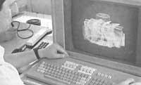
Thus, the determination of the three elements involved in the cutting process (i.e., part, machine and tool) allows the calculation of optimal cutting conditions to be completed. The aim of the cutting technology package is to achieve optimum cutting speeds, depths and breakthroughs, i.e. cutting conditions that result in the most economical operation. This module complements the CAM space. To do this, we proceed to the analysis of most of the process restrictions.
These restrictions are made up of machine characteristics, part material and tool itself. As for the machine, its power, speed limits and kneading of the part and tool can be mentioned. The material and shape of the piece delimit its rigidity and therefore its inclination. So much can be said of the tool. The material of the tool also sets the maximum force to break and its geometry sets depth and advance limits. The result of this module also determines the tool path.
All information regarding the cutting process will be stored in a file. Each record in this file saves the tool position and cutting conditions. A post-processor (PP) will turn this information into a numerical control instruction corresponding to the exact machine, the machining of the part being the next step.
As already indicated, since all the modules are connected to each other, it would be enough to enter the geometry of the part to, once the whole procedure is done automatically, obtain the list of numerical control instructions. On the other hand, since the reliability of the results of these programs is based on the introductory data, especially on those parameters that determine the behavior of the materials (which are not always rigorous enough), the user of the program could reject the results produced automatically by the program, as a consequence of the aforementioned inaccuracy.
In this case, using data from your experience, you can take the same steps that the program performs manually, always with ease to perform quick computer calculations. In this way you can complete the parallel path to the mentioned system, where the user himself determines the process planning and the selection of tools and cutting conditions.
This is the approach to the reality that is hidden behind the acronym that every day publishes mechanical engineering, in which we have only managed to confirm the reluctance mentioned at the beginning: We have come to discover that acronyms, in addition to institutions, taxes, definitions and trades, disguise other acronyms! Because, after all, the question what is CAD/CAM, being terrible, has a single correct answer: GI/CAPP/ATS/CTP/PP.
Within the framework of the CAE, the development and proliferation of computer programs called manufacturing systems aimed at the automation and integration of each stage of the manufacturing process has also begun. These systems have an increasingly broad technological base that allows them to obtain more reliable results.
The studies of understanding the cutting process, the focus of the manufacture of parts by chip start, have occurred since the moment this process reached the industrial scale, with the aim of obtaining the optimal conditions of the process. The development of tools and part materials, such as the increasing rigidity of the machine structure, has led to the advance of the area of cutting conditions, making possible situations that were previously impossible.
But the advance, in addition to the scope of the materials, has occurred in the manufacturing procedure. Here are the mentioned CAD/CAM systems.
During the manufacture of a part, we usually follow some specific steps or stages that take us from the design to the realization of the part. The aim of the manufacturing system is to take these steps with computer. Each stage is organized into a module and the output of one complements the input of the next.
Three elements are involved in every manufacturing process: machines, tools and parts. Once the machine has been delivered and the design of the part has been completed, five stages or stages can be distinguished throughout the manufacturing process by chip removal, which will complete the design of the part and the bridge until its realization:
- Introduction to geometry. (GI Geometry Input) Process
- Postprocessor. (PP Post Pro-cessor)
planning. (CAPP Compu-ter Aided Process Planning) Tool
selection. (ATS Auto-matic Tool Selection) Cutting
technology. (CTP Cutting Technology Package),
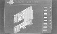
Therefore, once the geometry of the piece is made (its design), the computer is accessed. The GI geometric introduction module is, in short, a CAD system adapted for the type of part to be manufactured. Next to the piece you have to define the rough part, since the comparison of both elements will produce the volume to be mounted.
The incidence of sponging will address the module known as process planning. Its main function is to determine the operations to be performed in the boot volume and the corresponding fields. In addition, it must play another important role: to establish the order in which operations should be carried out, according to economic criteria and tolerances of the part. Thus, the CAPP combines CAD and CAM, since it uses elements of both concepts.


