

High speed train (AHT/TGV). At speed of airplanes on lanes through Europe
From the AHT brand to the brand in France. In this same magazine Elhuyar the previous articles have been published (nº 33, March 1990, 15/12). Page. and Núms. 37 to 38, from July to August 1990, 6. Page. ). See as an introduction the follow up box of this improvement of brand on duque.
Twenty-three years ago, Capitole, was driving 200 km/h from Paris to Toulouse on wheels. At that time, engineers showed that no normal commercial train circulating on the lanes in the hands of the calculation did not exceed that speed, since, if it exceeded, it had to pass to use air cushions or the magnetic one of the skiers.
Three months later, I... In Korea, in an international symposium, another large number of engineers launched, with the help of their equations and computers, the prediction that the current outlet through the catenary/pantograph system would never have been able to pass a speed of 450 km/h.
The French SNCF, at present, have surpassed this speed twice (at a speed of 482.5 km/h between Courtalain and Château-Renault, at kilometer 166 and beginning of June 1990, in a new experimental train without exploiting TGV Atlantic at a speed of 510.6 km/h). In both cases, it should be noted that conventional trains were responsible for obtaining the marks, that is, the models with the intention of circulating, although the second presented some improvements and changes for it (increase of wheels, reinforcement of motors, etc. ). ).
Maximum passenger train speeds Speed marks on lanesCommunications and Communications Communications
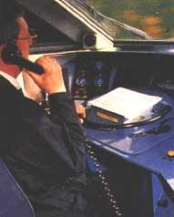
One of the main differences of these trains with respect to the current ones is their extensive communications system. This currently means a large number of computer and audiovisual equipment incorporated. In each branch there are 16 computers connected to each other that monitor all the functions of the train: traction, braking, signaling, interior environment, etc. To be able to control everything, the driver's room is full of control devices, offering at all times the input to the memory of all the data of failures and functions of each branch. All this information is transmitted by radio to the central control post of Paris 2 hours before the arrival of the train.
For this purpose a complete system of transmission beacons of 10 km is used along the entire length of the route. However, communication can be done through other systems. The preparatory operations in a branch have their watertight area directly under the orders of the Central Place of Paris, such as the adaptation along the route of the interior environment of the train, the information along the road for passengers, other routine controls, etc.
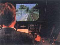
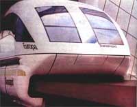
In the presence of the large black steering wheel, the driver's cabins and the drivers of these trains actually look like a flight pilots room that is prepared with the Giravion Dorand aeronautics simulator.
Rare handrails, grouped needles, solar/radio system, etc., maintain a constant relationship between the mechanic (conductor) and the Paris traffic regulator. However, most of the switchboards within the cockpit, however, are to give orders of air conditioning.
Catenary/pantograph
As for the catenary, they have logically had to make changes, but not with respect to the system. The system is the same, but they have had to stretch the catenary. This has been done in order to find a solution to this descendant. When using the catenary/pantograph system, this touch produces waves in the catenary whose speed of propagation depends on the mass of the cable and the tension of stretching.
In general and until reaching a speed of 450 km/h, this speed of propagation is usually higher than the speed of circulation of the train, but when the speed of circulation reaches and above all exceeds this critical value, the train detects the wave and this wave of the catenary causes the escape of the cable from the chain to the pantograph.
But they have also found the remedy to this problem, increasing the tension of the cable of the catenary and getting the speed of propagation of the wave to be greater than that of the train, that is, to circulate from that critical speed until now, they have solved the problem increasing the tension of stretching of the catenary. What was normally 2,000 daN (decanewton) has been elevated to 2,700 daN, which has allowed the speed of the wave in the chain cable to reach 520 km/h, somewhat higher than the speed of circulation reached (510.6 km/h). In this way the barrier of this system has been overcome for the moment in order to circulate above 500 km/h.
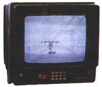
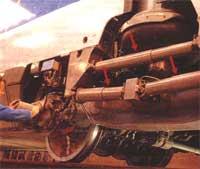
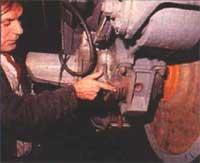
For the pantograph to rub properly and continuously the cable of the catenary at a speed greater than 500 km/h, video cameras have been installed and the pantograph tightens at your disposal the stretched cable of the catenary with sufficient pressure, without the catenary escape to the pantograph in the part of the undulation.
Therefore, those who spoke in Korea came up with something (though not everything) and announced catenary/pantograph system problems. Less did those who spoke at the time of the Capitole. Of course, these are not the current traffic speeds. It is currently 300 km/h which is considered the highest speed for normal circulation at high speeds. But the rest can arrive without much time. Therefore, it can be said that the train also approaches at minimal speeds of circulation of the planes.
On the other hand, the power required to circulate at these speeds of 13,000 kW is different from the prank of crossing the section of 1,5 cm 2 of the catenary cable and passing the pantogram. The contact pressure has its Joule effect in a contact section as small as the pressure. Therefore, the marks were made in winter (1989) or spring (1990) when the ambient temperature was cold or cool.
However, around 0ºC the air has a high density and the aerodynamic resistance increases. In any case M. According to Lacôte, the ideal ambient temperature would be around 10ºC, taking into account the temperature/state of the air, both for the catenary/pantograph system, and for autochronous motors and electronic automatism to be properly cooled and to function at the proper temperature, as well as for the aerodynamic resistance not to be too high.
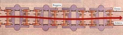
Particularities of bogie and lanes
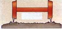
Aside from the necessary training and details of the autosynchronous motors that have had to be used to obtain these new brands, widely expressed in number 33 of Elhuyar, in this article, in addition to the bogies, I consider it appropriate to explain other details. The AHT train, like all modern trains, is mounted on two bogies, each with two axes. On these axes and their wheels hang the chassis of the motors (bogies) and on them the one of the vehicle (box).
However, the bogie does not go directly to the sides without moving when the wheels advance as the wheels spin (especially at those speeds). Turn to the sides a small angle with respect to its vertical axis, both to the left and to the right. In addition, it moves to height. This last movement is much more controlled by hanging docks, shock absorbers and elastic elements, and although the level of comfort that have reached these trains would deserve a thorough analysis of them, today at least we will avoid it and focus our attention on the lateral movement.
As he has said, the geometry of the entire rolling system is the one that has to move towards the sides keeping stable and at high speed. Therefore, the balance of the train is achieved in part by the circulation of pairs of conical profile wheels in the new lanes with both inclined towards the interior.
In this way, the bogie, a ball, is so strong on the lanes as on a piece of profile type V, so that the reactions between the two lanes allow to remove between themselves the force components that are directed to the sides and the movement trends that are derived from them, obtaining their best balance even when creating any lateral disturbance. It must be taken into account that the rail is not always a geometric straight line of level and that the turbulent aerodynamics constantly agitate both the traction elements and the trailers (whether they are wagons, train boxes or locomotives).
In addition, the bogies, depending on their looseness in the rail, circulate in zigzag according to a type of movement (such as the mordaces, but performing the balance through a longer path), although at high speeds and in very tight lanes there is a dimmed undulation.
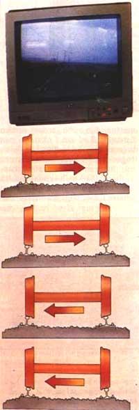
Thus, the width of the oscillation angle decreases along the length of the bogie, but when it functions as a more complete and larger set, the mass of its inertia increases to the blow and at the same time the action of inertia, making the oscillations (sinuous) smaller and more lazy and directing the bogie always towards the center of recirculation.
The reduction of the distance between two axes produces an inverse effect. Therefore, the best solution that has been found to date and that was accepted from the first AHT/TGV, has consisted of fixing the distance between axes in 3 m (being the lane of 1.435 mm). This bogie model has been suitable to withstand a speed of 500 km/h maintaining stability as the train advances. It must be said that the elimination of these strong lateral oscillations is the result of a complex system of elastic and cushioning joints very well calculated and long calculated.
This system, therefore, in addition to providing safety, is a great comfort for the whole vehicle. It is one of the secrets of the brand. Other previous models also reached relatively high speeds (in 1955 the machines 331 km/h BB and DC), but in a very undulating layout and under those conditions no further progress could be made. The oscillations of the bogies obliged enormously the lanes and from there the engineers concluded that the speed of safe circulation was not going to be able to exceed 200 km/h.
The installation of heavier lanes (60 kg/m of weight instead of 40 or 50 kg/m above) and the modification of its attitude to improve the speed of circulation has therefore been essential. For this reason, they have had to perform new reibos by curves and signaling. Currently, through the improvement of lanes and the implementation of damping systems against the oscillations mentioned in the bogies, these vehicles will be able to circulate without deforming a millimeter at a speed of 500 km/h (not even 300 km/h that for the moment is of circulation).
As for the intrinsic stability of the vehicle, therefore, one of the main reasons for success is the system of articulated elastic joints that present these TAV//TGV. Without this it would have been impossible to exceed 400 km/h in tests. Of course, the essential complement of this is a completely new, computer-controlled redesign. Although they have not yet been fully put into public service, the brands that are being overtaken day by day announce that they will soon arrive in our country.
Towards the year 2.000
However, the SNCF is working towards Europe in 2000. But there is something more in Europe and the world. In France, engineer Bertin has become a pioneer in trains hanging without pads. In Germany and Japan, engineers seem to have greater faith in the idea of magnetic excuse for high speeds.
This solution requires, of course, a path recirculated with electromagnets, that is, a very special infrastructure. Speaking only of speed (purely probative tests), with magnetic excuse material they have reached a speed of 435 km/h, but in this sense the TAV has more merit overcoming this speed with vehicles of series and normal circulation. In addition, the SNCF has found that it is possible to make long travel through high-speed trains, in addition to the railways to travel at different speeds. This has been developed for the moment mainly in France, but from now on its goal is all Europe, without forgetting other aspects of the world.
Zu idazle
Zientzia aldizkaria